11+ 4 bit adder circuit diagram 4 bit adder circuit diagram 4 bit adder circuit diagram
logic gates - How to make 2 bit or more half adder circuit - Electrical
Full adder circuit diagram 4 bit binary adder circuit diagram 4 bit adder subtractor circuit diagram
Adder half xor rangkaian logic ripple adders transistor kombinasi
4 bit full adder circuit diagram1 bit full adder circuit diagram Full adder truth table and circuit diagramFull adder circuit: theory, truth table & construction.
Logic gatesBinary adder and subtractor circuits: half and full adder, subtractor Adder bit circuit half make full logic gates first questions electronics cout second puzzle connecting solved which4 bit adder circuit diagram.

4 bit binary adder circuit diagram
Adder full circuit diagram using truth table carry 4bit construction schematic shown chip ttl ahead feature below look8-bit adder circuit diagram 1 bit full adder circuit diagramThe answer is 42!!: four bit full adder tutorial.
4 bit adder circuit diagramBit binary bits output geeksforgeeks incremented 8 bit full adder circuit diagram4-bit binary adder-subtractor.

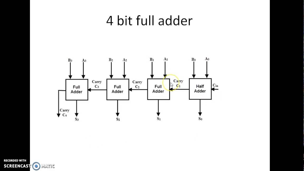
Circuit diagram of 4 bit full adder
4 bit full adder circuit diagramFull adder circuit diagram 4 bit full adder circuit diagram4 bit adder circuit diagram.
Binary adder and subtraction circuits along with its various typesAdder subtraction binary circuits Binary adder circuit diagramElectrical – 4ِ-bit adder in multisim – valuable tech notes.

Adder bit full four logic gates byte 4bit nand boolean not nor values possible possibilities hold answer trick function known
4 bit binary incrementer1 bit full adder circuit diagram Adder alu circuit given nor nand4 bit adder circuit diagram » schema digital.
4 bit full adder circuit diagram8 bit adder circuit diagram 8 bit parallel adderAdder lookahead vhdl verilog.

🎉 4 bit parallel adder theory. 5.9: four. 2022-10-30
.
.


4 Bit Full Adder Circuit Diagram

4 Bit Adder Circuit Diagram - Caret X Digital

Full Adder Circuit: Theory, Truth Table & Construction

8 Bit Parallel Adder
8 Bit Adder Circuit Diagram

4 Bit Adder Subtractor Circuit Diagram

logic gates - How to make 2 bit or more half adder circuit - Electrical
